So in the aftermath of failing to get my electret mic working (a fault which I am almost certain was with the on-board amplifier), I'm going to have to draw the cutoff at my analysis of the ArduinoFFT example code. Most of the last 2 weeks were spent on trying to diagnose the mic and failing, and subsequently digitizing my research notebook into blog form and writing up a quick summary of my research.
Look to the separate "Summary" page for the research report!
Sunday, December 15, 2013
Sunday, December 1, 2013
Week 14/15: Realtime FFT and Mic Issues
As a good portion of week 15 was spent digitizing my research effort, this posting will summarize my efforts over Thanksgiving break in addition to the week subsequent.
As I am home for Thanksgiving break, I do not have as much access to tools or equipment. Consequently I spent this week looking into a way to implement realtime FFT on the Arduino. If you recall my earlier assessments upon starting this research I was somewhat hesitant to perform any realtime signal processing. This feeling was compounded by having switched from the 80 Mhz chipkit processor to the reference 16 Mhz AVR earlier in development. However upon some cursory googling into the possibility of something simple like pitch recognition, it seems that something such as FFT is completely doable.
****An aside to clarify the reason for FFT research: I decided upon the tone recognition sensor concept detailed in a previous post. The reason for this is that it seems simple enough to implement, while avoiding possible complexities with communications on the 6 DOF position and movement tracker.
Having taken the ECE intro DSP course, I was somewhat familiar with the concept of pitch recognition via Fourier analysis of a sampled signal. However it had been awhile, and I saw fit to review it. After scrounging up some books, I found that the following link makes a pretty good summary without delving too deep into the complexity of the thing. (Reminder: Our goal is an easily implemented FFT, which is a computer-optimized DTFT, which will perform pitch identification).
http://www.arduinoos.com/2010/10/fast-fourier-transform-fft/
(All pages are interesting, but I don't think I'm going to use the code provided)
Now having explored that link, while the explanation of the concepts and algorithms is good, I am opting away from using his PlainFFT library. The reason for this being that it seems to be developed for more "hardcore" signal processing than we need, and it appears somewhat overcomplicated given that all we need is basic pitch recognition. Instead I decided upon using the ArduinoFFT library (http://wiki.openmusiclabs.com/wiki/ArduinoFFT) as it is simpler and much more straightforward to understand directly from the sample code. This covers the hard part, the software implementation of FFT. From here we just need to get the hardware up to speed.
The configuration for this only requires some form of audio input to be available to the arduino. The solution? A nice prototyping-centric electret mic from sparkfun! I happened to have one on hand, however upon testing it out it was returning garbage values, oh well back to software. (Plot spoiler: the mic was broken and I couldn't get one before the end of the semester)
Presuming that the ArduinoFFT library works smoothly, I'm going to overview the sample code for the library, posted here. This code performs fourier analysis on a sampled signal by repeatedly sampling the A0 channel of the Arduino's ADC during the execution loop. 256 total samples are collected, formatted, and then processed into a 128 element array. The output resides in fft_log_out and is transmitted to the Serial lines. Now having given the high-level picture, this code is very interesting and I want to point out some cool bits.
- The entire thing is performance based, and revolves around squeezing every bit of processing time out of the Arduino as possible. This is very critical to achieving high accuracy during signal sampling, incorrect or time-skewed data could lead to false results.
- This manifests itself through the use of multiple low-level statements throughout the code. All of the capitalized variables represent internal controls on the Arduino's ATMega328 MCU.
- In the initialization section, "TIMSK0 = 0" forcibly disables the Arduino's internal timing mechanisms, and also prevents any timer interrupts from engaging the processor. This optimization improves performance however, as the code will note, processes dependent on this function will be impaired. The delay() function is the victim here, and given this function's common use in Arduino development it may be prudent to store the value of TIMSK0, and restore it back to re-enable timing function OUTSIDE of the sampling function.
- The ADMUX control register determines the ADC channel to poll. As the code has it, 0x40 corresponds to analog channel 0. This isn't doable as we have A0 reserved for our I2C communication. As per the AtMega328 spec, the lower 4 bits of this register correspond to the MUX controlling the ADC channel, so the lower hex digit must be modified if another channel is selected. For example, 0x42 will set channel 2.
- cli() and sei() control the interrupt gating on the AtMega. This effectively shuts out all external interrupts from engaging the processor, preventing the sampling code from being interrupted. This has the potential to cause issues with our I2C comms, so I'm hesitant to leave it in. Receiving an I2C interrupt during sampling will cause it to be ignored, so the NXT side will have to implement some control cases in the event the Arduino fails to respond.
- The for loop performing the signal sampling appears to zero every other entry. I could be wrong, but I believe this is an optimization taking advantage of the fact that several signal terms are zeroed during the DTFT process. Either way, hooray because it's faster this way.
- Additional processing will need to be performed on the fft_log_out data set in order to extract a tone. The FFT will process the signal into its constituent frequencies, identification of the majority frequency should be easy enough to do.
Sunday, November 17, 2013
Week 13: Miscellaneous Brainstorming
A good part of this week has been devoted towards researching additional info on various things which have been worked into other blog entries. So most of this week's documentation has been distributed amongst the other posts.
One notable thing I've been throwing around is the possibility of RobotC multithreading. This could possibly reduce the latency of a sensor access from the NXT user program's perspective. By spinning up a background thread whose job is to continuously poll attached sensors, the data will be more or less constantly updated and available during the main execution loop. This is slightly more efficient than my current method of only polling the sensors at the start of each execution loop iteration. And it would also be good to understand how to multithread on RobotC anyways.
After looking into it (15-20 minute jam session), RobotC has a relatively simple multithreading implementation. It's referred to in RobotC as "multitasking", and it involves creating separate "Task" routines and then kicking them off with StartTask().
task main()
{
StartTask(Task1);
StartTask(Task2);
}
task Task1()
{
//Things
while() ;
}
task Task2()
{
//More Things
while() ;
}
Code 1. That's literally all you need to do to create a separate thread.
As can be seen, it's a relatively painless affair. However I do urge caution, in ANY user program ANYWHERE too much multithreading can be dangerous and resource intensive. Without proper understanding of how to multithread correctly, it may just be simpler to keep things iterative. I'm fairly sure RobotC doesn't implement any "high-level" control of multithreaded constructs (Mutexes/Semaphores), so keeping critical sections safe lies entirely on the programmer.
I may pursue this further to implement background sensor polling.
Sunday, November 10, 2013
Week 11/12: IR Sensor
Going off of my previous brainstorming regarding possible sensors, I decided to begin work starting with the IR sensor idea.
POST-COMPLETION EDIT: So it's probably best for my code to speak for itself here (link to both files at the bottom). I'm going to do a breakdown of both the RobotC and Arduino codes, pointing out anything important of note. I should note that the NXT and Arduino are connected as previously described, with the I2C lines feeding into the A4/A5 analog pins on the Arduino. There is an IR sensor signal line feeding in to DIO pin 4 on the Arduino with a 330 Ohm resistor in series.
LIBRARY NOTE: The IR sensor requires a decoding Arduino library written by Ken Shiriff (https://github.com/shirriff/Arduino-IRremote), the instructions to install are included on the github.
NXT Code
This section is fairly straightforward. There is a main execution loop, main(), which continually polls the Arduino using PollIR() to retrieve a 32-bit IR code. Once retrieved the code is displayed on the NXT screen, and a particular tone is played if the code matches pre-determined values (I'm using a random remote control I had lying around. Other remotes will have different codes).
The guts of the PollIR() function are also pretty standard. As detailed in previous posts, a register selection packet is constructed using the I2Cmessage[] structure selecting register 0x01 on the Arduino. The packet is send, a 4-byte reply (IR codes are 4-bytes long) is requested and retrieved using readI2CReply(), and some bitwise reconstruction is performed to get the original code. -1 is used as a reserved code to indicate that no new data is available from the sensor.
Arduino Code
The Arduino is responsible for continually scanning for IR codes, utilizing the newly installed IR photodiode. The <IRremote> library provides the "irrecv" structure, initialized with the line "irrecv.enableIRIn()"; this also prompts the library to begin scanning in the background of the user program. During each execution loop this structure will be evaluated for IR codes, upon detection they will be committed to memory. The Arduino needs to be capable of storing multiple IR signals, recall the NXT is not necessarily polling the Arduino in realtime, and thus there needs to be some mechanism to hold unprocessed codes. I implemented this functionality using a linked-list queue, and the push() pop() functions manage access to this.
The Arduino's Wire library is configured to use address 0x0A, and the I2CHandleDataRequest() and I2CReceive() functions are attached as interrupt handlers to be called when data request or register selection packets are received respectively. Recall that digital sensors maintain register banks; this is emulated with a register_requested state variable, selecting between register 0x01 (Most recent IR Code) or 0x02 (length of IR processing queue).
Mentioned previously is an idiosyncrasy of the Wire library, the Arduino will only transmit packets using 1-byte payloads. This means that any data must be transmitted as a series of disjoint byte packets. As IR codes are 4 bytes in length, I have a function constructIRArray() to take in a code and create a 4-element byte array for I2C transmission. Once this is transmitted, the RobotC code will perform reconstruction of the IR code.
One consideration to make is that I haven't put in any memory safeties. Here I'm presuming data will be processed in a timely manner, though if for some reason a massive number of IR codes were to accumulate without being polled by the NXT, there could ostensibly be memory errors as the IR queue will never be cleared.
Links to Code
Arduino Code - https://www.dropbox.com/s/ewd55d2vx574665/IR_Arduino.ino
NXT Code - https://www.dropbox.com/s/8yq10d8isjexdst/IR_NXT_Program.c
Sunday, October 27, 2013
Week 10: Exploring Sensor Ideas
Now that I have the groundwork for NXT-Arduino comms up and running, I've begun throwing around various ideas for custom sensors to implement. I've been throwing most of these ideas around in my head, and I'm going to very briefly identify the ones I feel are most viable, and jot down a few spurious ideas about each.
IR Receiver - This is a relatively simple idea and should be comparatively easy to implement. Attach an IR photodiode to the Arduino and run some processing on the signal. Then package the data for transmission to the NXT.
IR Receiver - This is a relatively simple idea and should be comparatively easy to implement. Attach an IR photodiode to the Arduino and run some processing on the signal. Then package the data for transmission to the NXT.
- Perform IR code processing through custom solution or pre-existing IR library
- Need to keep data processing asynchronous, will have to store results until NXT polls
- Needs some form of queuing structure, can infinitely expand (within memory limits)
- Sensor is useful for remote control of the bot, and IR remotes are everywhere
- Need to determine if code recognition is done on the Arduino or NXT side
- Possible problem with the A4/A5 analog pins on the Arduino being the only hardware I2C lines available. It should be possible to attach the the module and extend the bus on a particular sensor line, but I really want to keep separation between the NXT and sensors discrete. Software-side bitbanging of the protocol is an option here
- No need to store previous sensor values, can simply maintain a bank of 6 registers (3 per axis, per sensor means 6 total registers). NXT can address each register independently to access each of the two "sets" of available data (gyro or the accelerometer)
- Latency may become an issue given the real time nature of the sensor, to retrieve measurements along all DOFs will require three separate polls for three separate register accesses. The latency of consecutive I2C accesses can be factored out by driving multiple I2C buses and then running three parallel accesses instead of three consecutive accesses on the same line. The tradeoff is port use on the NXT.
Sunday, October 20, 2013
Week 9: NXT-Arduino I2C Interface Protocols
Now that I2C is working and we are capable of bidirectional data transfer at the behest of the master device, it makes sense for there to be some standardized protocol in play to govern communications.
To recap the working model I'm going with, the NXT is the bus master and will initiate communication with a sensor when polling it. This data transaction will first involve the NXT transmitting a "register selection" packet to the sensor, the payload of which will contain the address of the sensor register to retrieve. The sensor will, upon receipt, switch to the proper register. In my Arduino-side code, this is emulated with a state variable. It is important to note that the register selection packet does not instruct the sensor to do anything other than select a register. It is not until the NXT runs readI2CReply that a "data request" packet is send over I2C to the sensor, upon which the sensor replies with the data requested. At this point all communication should cease (maybe barring an ACK packet), and the bus will lie dormant until another poll begins.
Another critical piece of the data transfer process that I've been somewhat glossing over is the actual format of the I2C packet. While the Arduino's Wire library will handle most of the I2C nuts and bolts, abstracting the user from having to program it all, RobotC makes no such allowance. In RobotC the sendI2CMsg function accepts a ubyte pointer to an array containing entries which constitute an I2C packet. Like all packets this one consists of a header, and a payload. The header contains entries for message size and address, while the payload contains the packet's data.
An important note on the Arduino's Wire library, the transmission of data using the Wire.send() method will transmit whatever I2C bytes are passed to it. This is done with 1-byte payload packets for all data given; passing in an integer will result in data loss as it will overflow the 1-byte payload allocated for it. This can be overcome by splitting transmission data into multiple pieces, and then passing the send() method an array of bytes, this will be realized as a series of 1-byte packet transmissions back to the NXT. RobotC's readI2CReply() must have the size of this reply packet provided as an argument to ensure that all the sensor data is received properly.
To recap the working model I'm going with, the NXT is the bus master and will initiate communication with a sensor when polling it. This data transaction will first involve the NXT transmitting a "register selection" packet to the sensor, the payload of which will contain the address of the sensor register to retrieve. The sensor will, upon receipt, switch to the proper register. In my Arduino-side code, this is emulated with a state variable. It is important to note that the register selection packet does not instruct the sensor to do anything other than select a register. It is not until the NXT runs readI2CReply that a "data request" packet is send over I2C to the sensor, upon which the sensor replies with the data requested. At this point all communication should cease (maybe barring an ACK packet), and the bus will lie dormant until another poll begins.
| Fig 1. Diagram showing data transaction and change of register selection. |
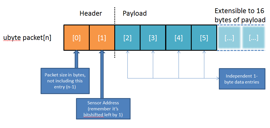 |
| Fig 2. General packet structure of a RobotC packet, to be transmitted by the NXT. |
An important note on the Arduino's Wire library, the transmission of data using the Wire.send() method will transmit whatever I2C bytes are passed to it. This is done with 1-byte payload packets for all data given; passing in an integer will result in data loss as it will overflow the 1-byte payload allocated for it. This can be overcome by splitting transmission data into multiple pieces, and then passing the send() method an array of bytes, this will be realized as a series of 1-byte packet transmissions back to the NXT. RobotC's readI2CReply() must have the size of this reply packet provided as an argument to ensure that all the sensor data is received properly.
Sunday, October 13, 2013
Week 8: I2C comms are working!
The majority of this week was spent hammering out issues with the NXT and Arduino. However it all paid off, and now the two devices are finally communicating over I2C!
Previously I had encountered an issue with the SDA line not being driven. This directed me towards the NXT, and upon close inspection it appears I had configured a pragma statement to use the wrong port. For reference, the relevant (and now correct!) line of code is:
#pragma config(Sensor, S1,TIR,sensorI2CCustom)
After debugging this and fixing it, the SDA line now drove data correctly and everything seemed okay on the NXT side. The issue now, infuriatingly enough, was that the Arduino did not seem to be receiving the data correctly. The code uploaded to the ChipKit was simple enough, a simple polling loop waiting for I2C data to come in. Through my debugging, I found that the packet receipt was being recognized, however none of the data was being decoded properly. Recall from the Lego I2C spec that the first packet transmitted by the NXT to a device simply contains the address of the register for the sensor to read/write. The info I was decoding on the ChipKit side was malformed or corrupted somehow, and it was mostly garbage.
To cut to the chase, I'm entirely unsure why the 022 libraries didn't work, and I gave up them. After a few hours of debugging I tried my own reference Arduino Uno on a whim, using an up-to-date Wire library to see if it would work. Surprisingly it did, and my data was now coming through cleanly. To cut my losses and prevent any more time from being wasted, I'm going to recommend using reference Arduinos from now on, and moving forward I'm going to ditch the ChipKit. This will allow me to use the most recent Wire library available, albeit the tradeoff will be fewer pins and a weaker processor.
Sunday, October 6, 2013
Week 7: The NXT has arrived!
I've received the NXT this week, and I am happy to report I've begun experimenting with my hardware.
After some software setup on the NXT side (The RobotC firmware must be burned to the NXT), I began by physically connecting the two devices. I did this by following the schematic referenced in my week 3 post, in which I fashioned a DIY connector after cannibalizing a sensor cable. My immediate goal is to establish simple communications, so I made my adapter pin-compatible to plug directly into the ChipKit itself.
With the physical connection out of the way, I proceeded to program each board with slightly modified but conceptually identical code to the one provided by the DexterIndustries site. Because Blogger doesn't handle formatting well, and because I'm going to include more polished electronic copies of my code in my final overview anyway, I'm not going to paste the code here as it would just waste space. I will however post the link to the code templates I'm using down below. The important part is that the Arduino and the NXT have been programmed for bidirectional I2C communication, with the NXT acting as the master device. This code follows the Lego spec for comms detailed in last week's post.
One really important thing is that the code posted on the dexter site seems to be designed for Arduino 1.0 or above. This is evident through the use of the v1.0 Wire.read() method, which is not available in the 022 libraries. Now the equivalent 022 method is Wire.receive(), which I've substituted into my code. Again this change is really important to note, because the ChipKit isn't talking with the NXT and I'm not sure why.
That brings us to the present, where I'm almost entirely certain that the messaging logic of my code is functioning correctly. My prediction is that some fault exists where I2C is handled, and thus I've hooked up my Saleae logic analyzer to the SDA/SCL lines. It appears that while the NXT it driving the SCL clock line correctly, there isn't any data being passed on the SDA data line. This indicates a fault with the NXT as the current RobotC code should initiate communications with an I2C packet addressed to the Arduino. However nothing is being sent, so here we are...
I'm going to continue analyzing the issue, until I can get the I2C into a working state everything is stuck on this.
http://www.dexterindustries.com/howto/connect-the-arduino-and-the-lego-mindstorms-together/
After some software setup on the NXT side (The RobotC firmware must be burned to the NXT), I began by physically connecting the two devices. I did this by following the schematic referenced in my week 3 post, in which I fashioned a DIY connector after cannibalizing a sensor cable. My immediate goal is to establish simple communications, so I made my adapter pin-compatible to plug directly into the ChipKit itself.
 | |
| A picture of my connector, note the 82KOhm pull ups soldered onto the header pins |
 |
| ....and socketed into the ChipKit |
One really important thing is that the code posted on the dexter site seems to be designed for Arduino 1.0 or above. This is evident through the use of the v1.0 Wire.read() method, which is not available in the 022 libraries. Now the equivalent 022 method is Wire.receive(), which I've substituted into my code. Again this change is really important to note, because the ChipKit isn't talking with the NXT and I'm not sure why.
That brings us to the present, where I'm almost entirely certain that the messaging logic of my code is functioning correctly. My prediction is that some fault exists where I2C is handled, and thus I've hooked up my Saleae logic analyzer to the SDA/SCL lines. It appears that while the NXT it driving the SCL clock line correctly, there isn't any data being passed on the SDA data line. This indicates a fault with the NXT as the current RobotC code should initiate communications with an I2C packet addressed to the Arduino. However nothing is being sent, so here we are...
I'm going to continue analyzing the issue, until I can get the I2C into a working state everything is stuck on this.
http://www.dexterindustries.com/howto/connect-the-arduino-and-the-lego-mindstorms-together/
Sunday, September 22, 2013
Week 6: NXT Sensor Data Spec
As I'm still waiting on the NXT, I went ahead and did some reading into how Lego currently communicates with their digital sensors. As we can directly control the I2C link we can implement the communications protocol however we want, but it's probably good to learn how it's performed as it is now.
Briefly summarizing what I learned, the Lego spec adheres to the master-slave rule that I2C normally operates with. The slaves will sit idly on the bus lines, happily processing whatever input they deal with. They will continue to do this until the NXT polls them for data, at which point they reply over I2C with a packet containing the relevant data. They then continue on without much pause. Now the interesting twist to this routine is that the digital sensors are capable of storing and receiving multiple data values.
To clarify, each sensor is responsible for maintaining a local bank of I2C accessible registers. These registers are updated with whatever data is relevant to the process that a particular sensor is performing. For example in a compass sensor, the sensor itself keeps a particular register updated with the current heading. When the NXT polls the compass, it will specify that register in its data request packet, at which point the sensor retrieves the register value and transmits it back to the NXT.
This is interesting because it opens the possibility for multiple data values to be processed by a particular sensor, while still keeping them accessible from the NXT. Particularly in our case, we could fold multiple sensor functions into our Arduino, and still only require one I2C line to return all of them. This also opens the possibility of bidirectional communication, allowing the NXT to send messages to the sensor to be processed. These could be configuration values, or they could be commands. For example the NXT could signal a particular color to be turned on in an LED strip, or the SSID to search for in a WiFi module.
A quick aside: just to make sure the ChipKit is working I uploaded some basic Arduino example programs to the ChipKit, everything seems to be fully compatible.
Idea: Wireless sensor capacity is possible, by linking an Arduino to the output of an I2C line as we're doing now. However instead of the sensor being locally attached, the Arduino can wirelessly interface through an XBee or WiFly controller, or even a Spark Core.
Briefly summarizing what I learned, the Lego spec adheres to the master-slave rule that I2C normally operates with. The slaves will sit idly on the bus lines, happily processing whatever input they deal with. They will continue to do this until the NXT polls them for data, at which point they reply over I2C with a packet containing the relevant data. They then continue on without much pause. Now the interesting twist to this routine is that the digital sensors are capable of storing and receiving multiple data values.
To clarify, each sensor is responsible for maintaining a local bank of I2C accessible registers. These registers are updated with whatever data is relevant to the process that a particular sensor is performing. For example in a compass sensor, the sensor itself keeps a particular register updated with the current heading. When the NXT polls the compass, it will specify that register in its data request packet, at which point the sensor retrieves the register value and transmits it back to the NXT.
 |
| Fig 1. Simple visualization of the register bank concept. |
A quick aside: just to make sure the ChipKit is working I uploaded some basic Arduino example programs to the ChipKit, everything seems to be fully compatible.
Idea: Wireless sensor capacity is possible, by linking an Arduino to the output of an I2C line as we're doing now. However instead of the sensor being locally attached, the Arduino can wirelessly interface through an XBee or WiFly controller, or even a Spark Core.
Sunday, September 15, 2013
Week 5: Doldrums
I'm still waiting NXT hardware, and so there isn't too much to report on this week. I'll keep it short: while I have the interconnect between the NXT and ChipKit laid out, I ran into the issue of not being sure how I'm actually going to physically connect the two together. It is possible to simply take a sensor cable and cannibalize it to expose the necessary outputs, and in all likelihood what I'll do for my purposes, however making a bunch of these connectors for classroom use is probably going to be a hassle and less reliable than a more...manufactured approach. Ideally I feel an RJ12 breakout would be the most suitable option, especially given that the class will implement any custom sensors on a breadboard.
To be completely honest I spent a good deal of time experimenting with EAGLE-CAD fashioning a connector to attach directly to the ChipKit. However for the sake of usable results here is a link to an open-sourced NXT connector breakout kit, with assembly available for an extra cost.
https://store.wayneandlayne.com/products/bricktronics-breakout-board.html
Sunday, September 8, 2013
Week 4: Software-side of the I2C communication
I haven't received the NXT for experimentation yet, and I apologize the next few entries may be somewhat short. In the meantime I've been covering some ground on how the software will implement I2C communication between the NXT and ChipKit.
Looking into the ChipKit, it appears that when they say "Arduino Compatible", they really mean Arduino-022 compatible. I'm not going to be sure if this is an issue until I test on hardware, but I just want to note that Arduino-022 and the related libraries are very much out of date. As of late 2011, the Arduino Foundation has released the much newer Arduino v1.0, and all library development has migrated to support that codebase. As many of the v1.0 core libraries are not backwards compatible with Arduino-022, I'm going to have to rely upon the older libraries. I'm not entirely sure what this spells for documentation purposes.
In particular, the library needed will be the Arduino Wire library. This is the Arduino library responsible for managing any hardware I2C function, and while it is possible to bitbang the communication in software, I'd rather stick with what is established. The Arduino Wire library is very straightforward, requiring the device to be initialized with an I2C bus address and communication interrupt handlers during the init() function. I'll explore this part later when I begin coding the ChipKit side.
On the NXT side, the RobotC API exposes two functions for handling I2C access. They are 'sendI2CMsg' and 'readI2CReply' respectively. The I2C send is fairly self explanatory, it will send a message packet on a particular sensor line (remember there are 4) to a particular I2C address. The readI2CReply will send a data request packet across the bus to a specified address, then proceed to receive a user-program specified number of bytes as a response. I will explore this in further detail once I begin NXT coding.
As an aside, I want to make note of an irregularity with the way the NXT handles I2C addressing. The Arduino must be initialized with a particular bus address, it can be anything but I2C only provides 7-bits of addressing so keep to that range. The NXT must be initialized with the same address so it knows where to address the packets it sends on the sensor data line. Even though the NXT and Arduino are directly connected, they are still operating with I2C and thus use address-based communication. However... the address provided to the NXT in RobotC must first be bitshifted left by 1 bit!!!! For example this makes an Arduino I2C address of 0x0A into 0x14, and so on the NXT side all packets will be addressed to 0x14, while the Wire library on the Arduino must be provided with 0x0A. I'm not sure why this irregularity exists, but I'm rolling with it.
Another aside: It should be possible to daisy chain multiple sensor devices off a single port due to I2C being a bus. I'm not going to explore this, but it's an interesting idea.
Also below is the link to the RobotC NXT API, which contains documentation for all NXT-related functions provided by RobotC.
RobotC NXT API:
http://www.robotc.net/support/nxt/MindstormsWebHelp/index.htm#page=nxt_functions/Sensors_Digital/Sensor%20Digital.htm
Sunday, September 1, 2013
Week 3: Examining the I2C Option
Now that I know I'm going to be communicating with I2C, I feel that a quick refresher is in order...more for my benefit if anything.
To briefly sum everything up, I2C (Inter Integrated Circuit) is a bus protocol that facilitates communication between embedded electronic components. The hardware side specifies a two-wire system, consisting of an SDA line (Serial Data) and an SCL line (Serial Clock), both pulled up to whatever logic level is used. All devices on the bus are connected to these two lines, and all communication occurs when a designated 'master' device initiates comms. As the protocol (and our implementation) has it, the master is the only device that can initiate communications, the slaves are entirely reactive.
In our system the NXT is the obvious choice to be the bus master. The way I envision the system working has the Arduino independently operating separate from the NXT as an I2C slave, to be polled for info when it is needed. The systems will obviously need to be connected, and thus I researched the pinouts for the NXT's sensor jacks. The lines very neatly expose the SDA/SCL lines in addition to Vdd and an AREF signal (GND). Given that the Arduino operates on a 5V logic level, the lines need to be pulled up with specific resistor values. Going off the suggestion of a site I found (link below), I am proceeding with 82K resistors. After all is said and done, we are left with the connection detailed below.
One possible issue which may be apparent in the above schematic is that the NXT provides 4.3 volts in its sensor lines. This may be an issue if the Arduino is picky about its logic level voltages, however I am of the opinion that the I2C facilities (and the Wire library) of the Arduino are capable of operating with such voltages.
It bears mentioning that I do not have the full suite of hardware yet, and am thus still in the planning stages. Until I receive all the necessary equipment, the next few posts may be somewhat sparse. In the meantime though I have a pretty monumental decision to make regarding the dev environment for the NXT. The main contenders are LabView for Mindstorms which operates using the graphical language NXT-G, or RobotC which utilizes traditional C. Having taken ECE 1882 I know how painful it is to use LabView on the NXT, and that I despise it with all my soul. Thus my completely unbiased and scientifically formulated conclusion is that RobotC be used at all costs.
Resource website with NXT-Arduino info, a good deal of my work is derived from here:
http://www.dexterindustries.com/howto/connect-the-arduino-and-the-lego-mindstorms-together/
To briefly sum everything up, I2C (Inter Integrated Circuit) is a bus protocol that facilitates communication between embedded electronic components. The hardware side specifies a two-wire system, consisting of an SDA line (Serial Data) and an SCL line (Serial Clock), both pulled up to whatever logic level is used. All devices on the bus are connected to these two lines, and all communication occurs when a designated 'master' device initiates comms. As the protocol (and our implementation) has it, the master is the only device that can initiate communications, the slaves are entirely reactive.
 | |
| Fig 1. Example I2C configuration from Wikipedia. |
In our system the NXT is the obvious choice to be the bus master. The way I envision the system working has the Arduino independently operating separate from the NXT as an I2C slave, to be polled for info when it is needed. The systems will obviously need to be connected, and thus I researched the pinouts for the NXT's sensor jacks. The lines very neatly expose the SDA/SCL lines in addition to Vdd and an AREF signal (GND). Given that the Arduino operates on a 5V logic level, the lines need to be pulled up with specific resistor values. Going off the suggestion of a site I found (link below), I am proceeding with 82K resistors. After all is said and done, we are left with the connection detailed below.
 | |
| Fig 2. Basic I2C connection between NXT and Arduino. |
It bears mentioning that I do not have the full suite of hardware yet, and am thus still in the planning stages. Until I receive all the necessary equipment, the next few posts may be somewhat sparse. In the meantime though I have a pretty monumental decision to make regarding the dev environment for the NXT. The main contenders are LabView for Mindstorms which operates using the graphical language NXT-G, or RobotC which utilizes traditional C. Having taken ECE 1882 I know how painful it is to use LabView on the NXT, and that I despise it with all my soul. Thus my completely unbiased and scientifically formulated conclusion is that RobotC be used at all costs.
Resource website with NXT-Arduino info, a good deal of my work is derived from here:
http://www.dexterindustries.com/howto/connect-the-arduino-and-the-lego-mindstorms-together/
Sunday, August 25, 2013
Week 2: Functional Requirements for the Communications Interface
Last week I investigated the NXT hardware, expanded upon some communications possibilities, and gave a very light preliminary assessment which leaned in favor of the RJ12 sensor ports currently used for COTS NXT sensors.
But before delving into further detail regarding comms, I'm going to take an aside and mention that Professor Anderson has provided me with the board I'll be interfacing with the NXT. While I've previously been under the assumption that the "Arduino" I'd be using was a reference Arduino Uno, I've been provided with a ChipKit Uno32.
Upon some reading from ChipKit's website this particular device appears to be a clone Arduino, which claims to be fully "Arduino-Compatible". At first glance it seems far beefier than a reference Arduino Uno, and touts more I/O pins, a more robust microcontroller IC (80 Mhz PIC controller vs the reference Uno's 16 MHz AtMega328 AVR controller), and also a variety of jumpers to configure various board functionality (power regulator/hardware SPI/etc.). I've never worked directly with a ChipKit board before, however I'm banking on the "Arduino-Compatible" part for ease of use.
Back on the comms side as I've previous mentioned, I have opted to go down the RJ12 route. The primary reason for this is that it is likely to be the most documented interface for the NXT, and there is no additional significant hardware required unlike the other approaches I've mentioned. To marginally hash out the factors involved in making this decision:
Research into current NXT sensors and their interfaces indicated that while the sensor ports are reconfigurable to a degree, the digital COTS sensors default to I2C based communication. And thus I2C it is.
But before delving into further detail regarding comms, I'm going to take an aside and mention that Professor Anderson has provided me with the board I'll be interfacing with the NXT. While I've previously been under the assumption that the "Arduino" I'd be using was a reference Arduino Uno, I've been provided with a ChipKit Uno32.
 |
| Fig 1. ChipKit Uno32 |
Upon some reading from ChipKit's website this particular device appears to be a clone Arduino, which claims to be fully "Arduino-Compatible". At first glance it seems far beefier than a reference Arduino Uno, and touts more I/O pins, a more robust microcontroller IC (80 Mhz PIC controller vs the reference Uno's 16 MHz AtMega328 AVR controller), and also a variety of jumpers to configure various board functionality (power regulator/hardware SPI/etc.). I've never worked directly with a ChipKit board before, however I'm banking on the "Arduino-Compatible" part for ease of use.
Back on the comms side as I've previous mentioned, I have opted to go down the RJ12 route. The primary reason for this is that it is likely to be the most documented interface for the NXT, and there is no additional significant hardware required unlike the other approaches I've mentioned. To marginally hash out the factors involved in making this decision:
- I need something workable fast, while I'd love to explore other communications options I'm limited in time and budget
- The likely scenario for this interface is during a class lab or other hands-on segment. Complexity would make achieving the overall goal, basic communications, needlessly difficult.
- The protocols in play are likely either SPI or I2C, and while I'm not an expert, I have experience working with both of these protocols.
- Needs to be capable of both synchronous and asynchronous communications
- Capable of scaling from simple sensor concepts to more involved (possibly DSP-heavy) sensors
- Not likely to be used for "high-speed" comms, here defining "high-speed" to be in excess of the capabilities afforded by I2C or SPI. However, should be capable of continuously passing data at a rate commensurate to the NXT's maximum sensor poll rate.
Research into current NXT sensors and their interfaces indicated that while the sensor ports are reconfigurable to a degree, the digital COTS sensors default to I2C based communication. And thus I2C it is.
Monday, August 19, 2013
Week 1: System Overview - aka: It Begins
Professor Anderson advised that I begin my research with some investigation of what I'll be working with. I agree that 9 out of 10 times it is in your interests to know what's going on. And so I began with a systems overview, and basic requirements analysis.
Now the overall goal can be stated pretty simply: Make the Arduino talk with the NXT.
Since whatever I decide to work with will revolve around what the NXT has to offer, I'll begin with some basic analysis of the NXT's hardware. Some cursory investigation yielded that the NXT is equipped with an ARM7 AT91SAM75256 embedded processor. The use of an ARM7 processor indicates that the NXT platform is deceptively robust, and among other things has native hardware support for communication options such as UART, USART, and SPI. The NXT itself is connected to a computer a la USB 2.0 cable, and the newer revisions (with which I am presumably working) appear to have bluetooth, though further investigation seems to indicate this is for remote programming and control of the NXT instead of for general use by the user program.
As far as embedded platforms go, the Arduino is fairly versatile. Any of the above communication options (UART/USART/SPI/BT) are viable to implement with the proper time and, in bluetooth's case, hardware. However all of these are relatively complex for what we need, and thus by the KISS principle I'm going to turn to the obvious low-hanging fruit: The RJ12 jacks already used by the NXT for sensor communication.
Now the overall goal can be stated pretty simply: Make the Arduino talk with the NXT.
 | |
| Fig 1. Eventually, the Arduino will be used to interface with custom sensor implementations, presumably breadboarded or developed as part of the new class. |
Since whatever I decide to work with will revolve around what the NXT has to offer, I'll begin with some basic analysis of the NXT's hardware. Some cursory investigation yielded that the NXT is equipped with an ARM7 AT91SAM75256 embedded processor. The use of an ARM7 processor indicates that the NXT platform is deceptively robust, and among other things has native hardware support for communication options such as UART, USART, and SPI. The NXT itself is connected to a computer a la USB 2.0 cable, and the newer revisions (with which I am presumably working) appear to have bluetooth, though further investigation seems to indicate this is for remote programming and control of the NXT instead of for general use by the user program.
As far as embedded platforms go, the Arduino is fairly versatile. Any of the above communication options (UART/USART/SPI/BT) are viable to implement with the proper time and, in bluetooth's case, hardware. However all of these are relatively complex for what we need, and thus by the KISS principle I'm going to turn to the obvious low-hanging fruit: The RJ12 jacks already used by the NXT for sensor communication.
 |
| Fig 2. The four RJ12 sensor ports in all their glory. |
Sunday, August 18, 2013
What is all of this?
Well, to put it briefly this work is part of a semester long undergrad research effort under Professor David Anderson (ECE Dept. at GT), as part of a larger effort to expand the Special Topics course ECE 1882 into a more developed survey course. As it stands this course is currently a 2-hour freshman offering which serves as an intro to computing systems, robotics, and to an extent, embedded platforms. The main feature of ECE 1882 is the design project, in which students utilize a Lego NXT controller to implement a robot capable of performing certain tasks whilst navigating an obstacle course.
That brings us to me, and my research project.
As great as the NXT is for an introductory robotics platform, it is limited in its COTS sensor capabilities. My goal is to take an Arduino-type microcontroller, so chosen for its comparative ease of use, and find a way to interface it with the NXT, the overarching goal being to develop custom sensors utilizing the Arduino.
This blog is a rehash of my research notes, jotted down during the project. What follows is a record of my work, put into blog form. Each entry will summarize my trials and tribulations for that week, along with any info deemed of importance. Think of this blog as a collection of musings as I progress through the project, I will have a separate page which clearly summarizes my results.
Subscribe to:
Posts (Atom)